
Wind is the load case that governs most aluminium curtain wall and cladding packages, yet it is frequently reduced to a single pressure figure in a tender document. That figure hides the engineering that actually decides whether a facade performs: the suction concentrated at corners and edges, the pressure coefficients that grow as the effective wind area shrinks, the deflection limit that keeps a gasket in compression, and the bracket and anchor capacity that holds the panel against uplift. This guide walks through the full chain for specifiers, facade engineers and importers — from how wind acts on a clad envelope, through the design pressure calculation to EN 1991-1-4 and ASCE 7-22, into panel thickness, fixings and bracket selection, then testing and the documentation a supplier should be able to produce before fabrication is released.
How Wind Loads Act on Curtain Wall and Cladding Systems
S1
Wind Pressure Fundamentals on a Curtain Wall Envelope
Wind acting on a building generates a pressure field that is anything but uniform. The reference quantity is the stagnation pressure — the dynamic pressure of the approaching flow, expressed in EN 1991-1-4 as q = 0.5 · ρ · vb² (with ρ ≈ 1.25 kg/m³ for air). A 45 m/s basic wind velocity yields a stagnation pressure on the order of 1.27 kN/m², before any shape or exposure factors are applied. Every facade design starts from this number and then distorts it through pressure coefficients.
The windward face sits under positive pressure as the flow decelerates against it, typically corresponding to net pressure coefficients in the range of +0.7 to +0.9 for a rectangular tower of moderate aspect ratio. The leeward face behaves in the opposite sense: flow separation at the windward vertical edges leaves a low-pressure wake, producing negative pressure (suction) of roughly −0.5 to −0.7. On a tall building the windward and leeward loads act in the same direction — both push the facade inward — so the total design load is the algebraic sum, not the windward value alone. For a building with an internal pressure coefficient cpi of ±0.2 (permeability through doors, louvres, and unsealed joints), the worst-case net pressure on a partly permeable envelope can rise by 20–30% over the sealed-envelope case.
Suction dominates the structural design of cladding far more often than pressure does. The critical zones sit at the corners and along the edges, where separation bubbles and vortex shedding concentrate the flow.
Why Corners and Edges Govern Panel and Fixing Design
Codes do not model facade pressure as a single average. EN 1991-1-4 divides each face into zones A, B, C, D and E, and ASCE 7-22 uses virtually identical corner, edge, and interior zones. The corner zone (A) and edge strip (B) carry local suction coefficients that can reach −1.8 to −2.5, compared with −1.0 to −1.4 in the field of the wall. In cyclonic regions these values are amplified further by the peak-gust factor.
Three consequences follow:
- Panel design. A 1.5 m × 3.0 m aluminium composite or insulated glass unit in a corner zone may see 2–3× the pressure of the same panel mid-wall. Glass thickness, stiffener layout, and composite panel skin bonding are all sized by the corner zone, not the average.
- Fixing design. Suction pulls panels away from the frame. Retaining clips, structural silicone bite, and pressure-plate bolts are sized in tension, and the corner-zone uplift governs the screw spacing and pull-out capacity of the sub-frame.
- Mullion and transom bending. Mullions spanning between floors see the highest tributary suction at building corners, where the member both spans and cantilevers at the edge return.
Aerodynamic Effects in the Built Environment
Isolated-building coefficients are a starting point, not the answer. Real sites modify the flow substantially:
- Shielding. Upwind buildings reduce the effective pressure on a facade — but shielding is unreliable for ultimate limit states, and codes commonly permit only partial reduction. A building that is unshielded in its first year of life may become shielded, or the reverse, as the surrounding urban fabric changes.
- Funnelling and channel effects. Narrow gaps between towers accelerate flow through the gap. Local peak pressures on the flanking surfaces can exceed isolated-building values by a factor of 1.3–1.8, with strong vortex shedding driving dynamic amplification.
- Topographic speed-up. On hills, ridges, and cliffs the wind speed increases with height above local ground. A 60 m ridge can produce a 20–40% speed increase at terrace level, translating to a 40–100% increase in pressure since pressure scales with velocity squared. Coastal sites add the roughness change from sea to land, which raises the gust factor at the shoreline.
- Turbulence and buffeting. Urban boundary layers are turbulent; gust buffeting imposes cyclic loading on panels, gaskets, and anchors. Fatigue-sensitive fixings and low-stiffness panel systems must be checked for dynamic response, particularly where vortex shedding occurs on tall slender towers or at re-entrant corners.
From Wind Pressure to Structural Demand
Once net pressures are known, the cladding design chain resolves into discrete checks:
- Panel bending: glass, aluminium sheet, or composite skin bending stress and deflection under tributary pressure.
- Mullion and transom spans: bending stress and deflection over the governing span between anchors or between transoms.
- Brackets and anchors: pull-out, shear, and edge distance in concrete or steel substrate. Post-installed anchors are often the weak link under alternating suction.
- Movement joints and gaskets: compression set, sealant strain, and air infiltration under repeated deflection cycling.
Deflection limits are the pivot between strength and performance. Typical practice uses L/180 for spans up to about 4.5 m, L/240 for longer spans, and L/360 where brittle finishes or tight seals are specified; glass-supporting members frequently fall under the stricter limits. The choice is not cosmetic — a mullion that passes stress checks but deflects at L/120 will open gasket compression and leak.
Serviceability, Watertightness, and Regional Exposure
Facade elements are governed by two limit states:
- Ultimate limit state (ULS): strength and stability — panel fracture, member yielding, anchor pull-out, buckling of stiffeners. Analysed under factored wind pressure, typically 1.4–1.5 on the wind action.
- Serviceability limit state (SLS): deflection, movement, vibration, and watertightness. Analysed under unfactored characteristic wind pressure.
Watertightness is where the two states meet. The gasket or wet-seal line resists water only while it remains in compression. Deflection under design wind opens that compression, and a facade that satisfies ULS stress checks can still leak under SLS gust loading. This is why AAMA 501 and EN 12154 watertightness tests are run at progressively increasing pressure differentials, and why L/240 or L/360 limits are often written into specification rather than left to the contractor’s discretion.
Regional exposure changes the numbers substantially. Cyclonic regions — the Gulf, northern Australia, the Philippines, parts of coastal China — specify much higher basic wind velocities and add cyclic pressure cycling for fixings, because sustained suction reverses. Temperate inland sites use lower basic velocities but can still carry high local suction on exposed corners. Exposure categories (ASCE 7 Exposure B, C, D; EN 1991-1-4 terrain categories 0–IV) modify the pressure by 30–80% for the same building geometry. Facade designs must be matched to the governing exposure at the site, not to a default.
| Behaviour | Windward Face | Leeward Face / Wake | Corner and Edge Zones |
|---|---|---|---|
| Pressure sign | Positive (inward) | Negative (outward suction) | Strong negative (outward suction) |
| Typical cpe range | +0.7 to +0.9 | −0.5 to −0.7 | −1.8 to −2.5 (zone A/B) |
| Relative magnitude | Reference case | ≈ 0.7× windward | ≈ 2–3× windward |
| Primary structural demand | Panel bending, mullion compression, inward push on anchors | Panel uplift, clip tension, mullion reversal | Panel uplift, retaining clip pull-out, anchor tension, local member bending |
| Governing limit state | ULS strength; SLS deflection of spans | ULS anchor pull-out; SLS gasket compression | ULS pull-out and local buckling; SLS watertightness under cycling |
| Design action | Size panels and transoms | Size clips and negative-pressure fixings | Size sub-frame, corner mullions, and anchor spacing in tension |
The practical takeaway: a curtain wall sized only on average windward pressure will under-design its corners and its fixings. The wind load case that governs a facade is almost always the local suction at the building edge, combined with the deflection that suction imposes on the gasket line.

Calculating Design Wind Pressure for Facade Panels
The Core Calculation Chain
Every curtain wall wind load calculation, regardless of jurisdiction, follows the same logical chain. The variables change name and the factors change value, but the sequence is fixed:
- Basic wind velocity vb — the fundamental wind speed for the site, read from the national annex or code map. In EN 1991-1-4 this is vb = cdir × cseason × vb,0, where vb,0 is the fundamental value from the national annex map, typically expressed as a 10-minute mean at 10 m height in terrain category II, with a return period of 50 years.
- Reference velocity pressure qb = ½ρvb². Using ρ = 1.25 kg/m³, a 26 m/s basic velocity gives qb ≈ 0.42 kPa. This is a reference value only — it is not yet the design pressure.
- Exposure / roughness factor ce(z) accounts for terrain roughness and height above ground. It can be decomposed as ce(z) = [1 + 7Iv(z)] × cr²(z), where cr is the roughness factor and Iv is the turbulence intensity. This is where terrain category and building height enter the calculation.
- Peak velocity pressure qp(z) = ce(z) × qb. For a 60 m building in suburban terrain, ce(z) typically falls in the range of 2.0 to 2.6.
- Pressure coefficient cpe,c10 — the external pressure coefficient for 10 m² reference area (the “c10” suffix), modified for the actual tributary area of the element being designed.
- Net design pressure w = qp(z) × (cpe + cpi), where cpi is the internal pressure coefficient. For maximum suction on the cladding, the windward external face is in suction and internal pressure is positive, so the two add rather than cancel.
Which Standard Governs, and What Each Contributes
Facade engineers work across several wind codes, and curtain wall projects sourced internationally frequently require checks against more than one.
- EN 1991-1-4 (Eurocode 1, Part 1-4) — the primary European wind action standard. It defines the qb → qp chain, the terrain categories 0 through IV, the cpe,10 and cpe,1 coefficients for walls and roofs, and the structural factor cscd. It deliberately leaves the numerical value of vb,0 to national annexes.
- BS EN 1991-1-4 and national annexes — the UK National Annex sets vb,0 = 23 to 27 m/s depending on region. Other national annexes (German, Dutch, French) each publish their own vb,0 maps, terrain roughness parameters z0 and zmin, and in some cases altitude and directional factors. You cannot design a European facade without knowing which national annex applies.
- ASCE 7-22, Chapters 26 to 30 — the US framework. It uses a velocity pressure qz = 0.613 KzKztKdV² (SI form, in Pa), with exposure categories B, C and D, topographic factor Kzt, and ground elevation factor Ke. Chapter 30 governs components and cladding, using GCp values read from figures that are explicitly plotted against effective wind area. For small panels, GCp rises sharply.
- AS/NZS 1170.2 — the Australian/New Zealand standard, mandatory in cyclonic regions where regional wind speeds Mz,cat are multiplied by climate change multipliers Mc, and cladding design pressures are further increased by local pressure factors Kl for edge and corner zones. Cyclonic region projects carry materially higher design pressures than equivalent non-cyclonic sites.
- GB 50009 — the Chinese load code. Foreign projects manufactured in China and checked locally are frequently verified against GB 50009, whose basic wind pressure w0 is defined at 10 m in terrain category B with a 50-year return period, and whose shape coefficients μs and height variation coefficients μz play the role of cpe and ce. Chinese manufacturers are well versed in GB 50009 and can cross-check an EN or ASCE result against it as a sanity check, but GB 50009 values should not be substituted for the specified design code without written agreement.
Effective Wind Area: Why Small Panels See Higher Pressures
Wind pressure does not act as a uniform block. It arrives as a turbulent field of pressure fluctuations, and the peak suction on the facade occurs over a localised area — typically a few square metres near a corner or edge. The larger the area you average over, the more the peaks cancel against the troughs.
This is the entire basis of the effective wind area concept. A 1.5 m × 1.5 m aluminium panel (2.25 m² tributary area) is exposed to a peak coefficient that may be 40 to 60 percent higher than the cpe,10 value for a 10 m² reference area. A single panel design pressure is therefore governed by a much higher coefficient than the value a whole-facade check would use.
Practical implications for the three design levels:
- Panel (glass or aluminium cassette) — smallest tributary area, highest coefficients, governs glass thickness, panel stiffener design, and the pressure on gaskets and cover caps.
- Mullion and transom — tributary area is the span × half the distance to the adjacent mullion on each side. Intermediate coefficients.
- Facade as a whole / main structural frame — very large effective area, coefficients approach the cpe,10 values. Not the controlling case for cladding elements.
A common error in tender-stage facades is designing mullions to the whole-facade pressure and panels to the same value. In practice the panel and its immediate fixings see the highest pressure on the elevation, and this is where local pressure factors compound the problem.
Terrain and Exposure: The Trend, Not the Number
Wind speed increases with height above ground, and it increases faster over open terrain than over rough terrain. Terrain categories run from open sea and smooth coastline through open country, suburban and urban, each with its own roughness length z0 and minimum height zmin.
The trend to hold in mind:
- A coastal site with open-water fetch reaches full wind speed at lower height and produces the highest ce(z) for a given height. Design pressures on a 60 m coastal tower can be 30 to 60 percent higher than the same tower in dense urban surroundings.
- Suburban terrain is the common default. A 60 m building in suburban terrain typically sees ce(z) around 2.0 to 2.6 depending on the code and the national annex.
- Urban terrain with tall surrounding buildings reduces the exposure factor but introduces channeling and downwash effects between buildings that the code coefficients do not fully capture. Wind tunnel testing is warranted for tall or complex urban projects.
- An escarpment, ridge, cliff or embankment creates a speed-up effect. EN 1991-1-4 handles this with the factor co(z) applied to the velocity; ASCE 7 handles it with the topographic factor Kzt. On a site close to the crest, Kzt or co² can push design pressures up by 10 to 25 percent or more. This is site-specific and must be assessed, not assumed.
Internal Pressure cpi: Sealed Versus Permeable
A truly sealed curtain wall envelope has negligible internal pressure. Ribbon windows, ventilated rainscreen cladding, louvred plant zones, openable windows and unsealed construction gaps all introduce permeability, and where wind pressure on one face exceeds another, the internal pressure rises.
- Sealed facade — cpi is typically taken as 0 or a small value (±0.2). In most sealed curtain wall designs, internal pressure is ignored for the panel itself.
- Permeable facade — EN 1991-1-4 uses cpi = +0.2 or −0.3 depending on the openings on the windward and leeward faces. Where a dominant opening exists on the windward face (a broken window, an open roller door, a permanently open louvre), the internal pressure coefficient can approach cpe for the windward wall, effectively doubling the net pressure on a panel or fixing.
- Dominant opening scenario — this is a design case, not a coincidence. Where an opening larger than 30 percent of the wall area is likely, the internal pressure should be taken equal to the external pressure at the opening. This governs the design of fixings and anchors near that opening, and it must be flagged in the calculation sheet.
For maximum suction on the cladding, cpi is added to cpe, not subtracted. Getting the sign convention backwards understates the design pressure and is a recurring source of facade failures during storm events.
Local Pressure Factors for Cladding Attachments
Coefficients from the main tables apply to broad areas. Attachments within an edge or corner zone attract higher local pressures because the pressure field is most intense there and because a single bracket failure propagates a larger area of cladding. Two approaches are commonly used:
- AS/NZS 1170.2 uses explicit local pressure factors Kl — typically 1.5 for edge zones and 2.0 or higher for corner zones — applied to the net pressure for the cladding element and its immediate fixings.
- EN 1991-1-4 and ASCE 7 handle this through the cpe,1 coefficient (the 1 m² value) and the GCp figures, which rise steeply at small areas. The effective area approach naturally produces higher coefficients in edge and corner zones, provided the designer uses the correct local tributary area for each bracket or panel.
The practical rule: the pressure used to design a bracket is not the pressure used to design the mullion it supports. Brackets and anchors within one panel width of an edge or corner should be designed for the local pressure factor applied to the peak coefficient, not the average.
Worked Example (Illustrative Numbers)
The following is a purely illustrative worked example using round numbers. It is intended to show the calculation chain and the relative magnitude of each step — it is not a substitute for a site-specific calculation to the governing code.
| Step | Parameter | Value | Notes |
|---|---|---|---|
| 1 | Basic wind velocity, vb | 26 m/s | Illustrative national annex value, 10 min mean, 10 m, terrain cat. II |
| 2 | Air density, ρ | 1.25 kg/m³ | EN 1991-1-4 default |
| 3 | Reference velocity pressure, qb = ½ρvb² | 0.42 kPa | ½ × 1.25 × 26² = 423 Pa |
| 4 | Exposure factor, ce(z) at z = 60 m | 2.3 | Illustrative suburban terrain, 60 m height |
| 5 | Peak velocity pressure, qp = ce(z) × qb | 0.97 kPa | 2.3 × 0.42 |
| 6 | External coefficient, cpe,c10 (corner zone) | −1.8 | Suction, corner zone, local effective area |
| 7 | Internal coefficient, cpi | +0.2 | Permeable facade, windward leakage |
| 8 | Net pressure, w = qp × (cpe + cpi) | −1.94 kPa | 0.97 × (−1.8 + 0.2) |
| 9 | Local pressure factor (attachment, corner) | 1.4 | Illustrative factor for brackets within the corner zone |
| 10 | Design pressure for bracket | −2.72 kPa | 1.94 × 1.4 |
The step from 1.94 kPa at the panel face to 2.72 kPa at the bracket is among the most under-appreciated transitions in facade design. Bonded or mechanically fixed brackets in a corner zone carry a design pressure roughly 40 percent higher than the panel they support.
Documentation and the Manufacturer Interface
A wind load calculation sheet for a curtain wall package should be a standalone, auditable document. It typically contains:
- Project location, building height, terrain category, and the governing code and national annex stated explicitly.
- The basic wind velocity and its source reference (clause and table from the national annex).
- The full qb → qp chain with intermediate values tabulated, not summarised.
- A pressure zone diagram — a facade elevation dimensioned with the corner, edge and field zones and the pressure applicable to each.
- A table of design pressures by element: panel, mullion, transom, bracket, anchor, and any dominant-opening scenario pressures.
- Assumptions on internal pressure, permeability, and whether a dominant opening case has been applied.
- Dead load, live load, thermal and seismic combinations where these interact with wind, and the load combination factors used.
Before the manufacturer can design brackets and anchors, the engineer must issue, in writing:
- Net design pressures in kPa for each zone — panel, mullion, transom, bracket, and anchor, as separate values.
- The governing load combination (for example 1.0 × wind for serviceability, 1.5 × wind or the applicable code factor for ultimate strength).
- Whether the design is based on permissible stress or load and resistance factor methodology, and the corresponding material safety factors.
- The deflection limit for the mullion (commonly L/175, L/240 or a project-specific value) and whether it is a serviceability or strength limit.
- The effective wind area assumed for each element, because the manufacturer must match panel and fixing capacities to the correct tributary area.
When this information is issued clearly, the manufacturer can size brackets, anchors and mullion profiles directly from the pressure table without re-deriving the wind load. When it is not — or when a single number is given for the whole facade — the manufacturer is forced to assume, and the typical result is a conservatively heavy or unconservatively light system that costs the project either money or performance.

Specifying Panel Thickness, Fixings and Brackets
From Design Pressure to Panel Thickness
Panel thickness is not chosen from a catalogue — it is derived from the net design pressure, the panel’s support condition, and the governing deflection limit. For aluminium cladding the deflection criterion almost always controls before stress does, because the elastic modulus of aluminium (about 70,000 N/mm²) is roughly one third that of steel.
Three variables drive the calculation:
- Spanning condition. A panel fixed on all four edges behaves very differently from one on two opposing edges. Continuous (multi-span) support along an edge reduces the effective span and the bending moment substantially compared with a single simply supported span of the same length, so a continuous cassette can often run a lighter gauge for the same pressure.
- Effective span. This is the clear distance between fixing centrelines, not the panel size. A 25 mm return flange on a tray panel does not reduce span — it only stiffens the edge. Failure to use the true clear span is the single most common source of under-designed cladding.
- Stiffener ribs. Where the span/deflection ratio cannot be met by thickness alone, hat-section or Z-section stiffeners are mechanically fixed or bonded to the back of the panel. They are cheaper than going up a gauge and keep the visible face geometry unchanged.
Typical progression for aluminium cladding panels (2.0 mm to 4.0 mm) is shown below. Treat it as orientation only — every project requires its own calculation.
| Net design pressure (kN/m²) | Typical panel thickness | Stiffening guidance |
|---|---|---|
| ≤ 1.0 | 2.0 mm, spans ≤ 900 mm | Plain tray or cassette; no ribs if edge returns are continuous |
| 1.0 – 1.5 | 2.0 – 2.5 mm | Ribs required above ~900 mm span; 2.5 mm for single-span trays |
| 1.5 – 2.5 | 2.5 – 3.0 mm | Ribs at 400–600 mm centres, or 3.0 mm plain with spans ≤ 1000 mm |
| 2.5 – 4.0 | 3.0 – 4.0 mm | 4.0 mm cassettes usually uneconomic — prefer 3.0 mm plus a ribbed sub-frame |
| > 4.0 (high-rise, corner zones) | 4.0 mm or composite build-up | Ribbed cassette with double return, or switch to composite panel with engineered sub-frame |
Typical guidance for preliminary sizing only. Confirm with project-specific structural engineering to EN 1999-1-1 and the governing national annex.
Allowable Stress, Deflection and Alloy Temper
Design to EN 1999-1-1 uses partial factors on resistance rather than a simple allowable stress. For non-weldable sheet alloys in the H14/H16 tempers, the 0.2 % proof strength is typically 110–145 N/mm²; for 6061-T6 extrusion it is around 240 N/mm², and for 5754-H22 sheet around 130–160 N/mm². The partial factor γM1 is normally 1.10, and γM2 of 1.25 applies in the heat-affected zone of welds — which is why welded mullion splices are avoided wherever possible.
Temper matters as much as alloy. 3003-H14 (work-hardened) and 3004-H34 are the workhorses for painted and anodised cassette faces: good formability, predictable strength. 5005 and 5754 offer better corrosion resistance at slightly lower strength. 6061-T6 is used for structural extrusions and brackets where stiffness governs. Annealed (O temper) material should never be specified for exposed panels — its proof strength is roughly one third of the H14 condition and it will yield under design wind.
Deflection limits are usually set by the facade specification, not the code: L/90 to L/120 for aluminium cladding panels, and L/175 to L/250 for mullions and transoms, with tighter limits (L/360) where brittle glazing or sealant joints are involved. These limits are serviceability criteria and must be checked independently of the strength check.
Mullion, Transom and Thermally Broken Profiles
Mullion and transom depth is selected by moment of inertia, not by section area. Required stiffness scales with pressure × span³ / (deflection limit × E), so a long span demands a disproportionate increase in section depth. Practical outcomes:
- Spans up to 3.0 m: 60–80 mm deep mullion, typically I ≈ 40–80 cm⁴.
- Spans 3.0–4.5 m: 100–130 mm deep, I ≈ 120–250 cm⁴.
- Spans beyond 4.5 m: 150–200 mm deep, often a two-part or reinforced profile.
Thermally broken profiles carry a structural penalty: the polyamide or PU isolator is weaker than the aluminium it replaces, and the manufacturer’s published moments of inertia for the coupled section are typically 30–50 % lower than the geometric sum of both halves, depending on whether the strip is a full shear-transfer type or a non-structural cap. Always design against the coupled-section values supplied by the extruder, and never assume the two aluminium halves act compositely unless the profile is certified as such.
Fixings, Brackets and Anchors
Bracket type follows the substrate:
- Helping-hand brackets — bolted to the slab edge or soffit with mechanical anchors; the standard adjustable fixing for unitised and stick systems.
- Cast-in channels — preferred on new concrete frames; high tolerance for bracket position and excellent pull-out capacity.
- Chemical anchors — used for retrofit and where edge distances are tight, but highly sensitive to hole cleaning, moisture and concrete condition.
An anchor must be checked separately for dead load (vertical, often with a friction-reduction factor), wind load (reversible, tension and compression, checked for fatigue in high-rise and for combined tension plus shear) and seismic demand (cyclic, with ductility and displacement requirements). These are combined per the governing load case, not simply added. Critical edge distances are typically 1.0–1.5 × anchor spacing and 6–12 × anchor diameter from a free edge; pull-out capacity falls off sharply below these values.
Safety factors on anchoring are commonly 3:1 to 4:1 on the tested ultimate capacity, and on-site pull tests (typically to 1.5 × the design working load) are essential because drilled-in capacity in a real slab varies far more than the datasheet suggests. Every project should specify a test frequency — commonly 1 in 10 or 1 in 50 anchors, plus 100 % proof testing where anchors are critical.
Movement, Tolerances and Corrosion
Aluminium expands at approximately 23.1 × 10⁻⁶ per K, close to double that of steel and concrete. A 3 m panel experiences about 4.2 mm of movement over a 60 K service temperature range — a real number that must be absorbed, not restrained. Fixing systems should therefore separate the functions: dead load taken by a fixed bearing point, wind and seismic restraint by slotted or floating brackets, and inter-storey drift (typically h/200 to h/400) plus live-load slab deflection accommodated by slotted holes, serrated washers and sliding shims. Threaded fasteners must never be tightened so that the panel is clamped against a bracket it cannot slide against.
Where aluminium contacts stainless or galvanised steel, isolate with nylon or EPDM pads and use stainless fasteners. Specify A2 (304) stainless for inland and low-chloride locations and A4 (316) for coastal, marine and de-icing-salt exposure; A4 resists pitting and crevice corrosion far better in chloride environments. Aluminium-to-aluminium joints still need isolating to prevent abrasion and fretting.
Specifier’s Checklist for the Supplier
- Design pressure: net (positive and negative) in kN/m², with the governing ultimate and serviceability values stated separately.
- Deflection limit: panel L/90–L/120, mullion L/175–L/250 — confirm the exact specified value.
- Panel size and support condition: module dimensions, clear spans, single or continuous support.
- Alloy and temper: for example 3003-H14, 5754-H22, 6061-T6, with certificates of conformity.
- Finish system: PVDF (typically ≥ 70 % Kynar resin) coating thickness, or anodising class such as 20 µm AA20, with salt-spray and weathering test data.
- Fixing type: bracket, anchor and fastener schedule, including material grades (A2/A4) and isolation details.
- Test evidence: structural pull-out test reports, air and water infiltration to EN 12153 / EN 12154, wind resistance to EN 12179, and any seismic or fatigue testing.
Testing, Compliance and Documentation for Wind Resistance
The Standard Test Sequence for Curtain Wall Performance
Curtain wall systems are validated through a defined sequence of laboratory tests, each isolating a different failure mode. The sequence matters: air infiltration and watertightness are assessed before structural performance, because a system that leaks at low pressure will leak worse once it has been loaded. Testing a specimen that has already been cycled to design wind load and back again can mask leakage paths that only open under deflection.
The core tests are:
- Air infiltration — EN 12153 (European) or ASTM E283 (North American). Measures the volume of air passing through the assembly at a defined pressure differential. This verifies gasket compression, seal continuity and the effectiveness of the drainage and pressure-equalisation design. It also has an energy implication: uncontrolled infiltration bypasses the thermal performance the system was specified to achieve.
- Watertightness under static pressure — EN 12154 or ASTM E331. Water is sprayed onto the specimen while a pressure differential is applied, simulating wind-driven rain. The test proves the drainage paths, baffles and weeps function as designed.
- Watertightness under dynamic pressure — AAMA 501.1. The specimen is sprayed while a calibrated propeller applies cyclic pressure pulses. This is a fundamentally harsher test than the static version.
- Structural performance / wind resistance — EN 12179 or ASTM E330. The specimen is loaded in increments up to the design pressure, then to a defined safety overload (typically 1.5× design pressure). Deflections are measured and compared against the specified limits, usually L/175 or L/240 for framing members, and tighter for glass edges. After the overload, the specimen must show no permanent deformation, no failure of anchors or interlocks, and no glass breakage.
- Safety and interlock testing — verifies that glazing retains in its rebate, that pressure plates and cover caps do not disengage, and that opening vents remain captive under load. This is where a system that performs well in the serviceability checks can fail, because interlocks engage only at or near ultimate load.
For opening elements, the sequence is supplemented with EN 12210 for resistance to wind load of the operable unit, and EN 12155 for its watertightness.
Why Watertightness Is Tested Below Structural Design Pressure
Watertightness is deliberately tested at a fraction of the structural design wind load. A facade is designed structurally for a peak gust pressure that represents the ultimate limit state, but the same facade must remain weathertight at ordinary storm pressures, which are far lower. A specimen tested only at full design pressure would tell you almost nothing about how it behaves during the vast majority of its life, spent at serviceability-level pressures and intermittent driving rain.
The result is the pressure ladder: watertightness is commonly specified and reported at multiple rungs, for example 0.25×, 0.5× and 1.0× of the structural design pressure. Each rung answers a different question. If the system holds at 0.25× but fails at 0.5×, the drainage system is being overwhelmed at a pressure level the building will see regularly. If it holds at 1.0×, it survives the extreme event.
For specifiers, the practical consequence is that a watertightness rating must be read together with the design pressure it was measured at. A statement such as “watertight to 1200 Pa” is not meaningful without the reference pressure and the test method. Always require the test report to state the method, the applied pressure differential, the duration and the spray rate.
Dynamic vs Static Water Testing
AAMA 501.1 applies pressure pulses (positive and negative) simultaneously with the spray, using a propeller to generate a fluctuating pressure field across the specimen. Static testing, by EN 12154 or ASTM E331, applies a steady differential.
Dynamic testing is more representative of real wind-driven rain, because wind pressure at a facade is not steady — it fluctuates with turbulence, gusting and vortex shedding. Static tests can allow a water film to stabilise in a way that never happens on site. For this reason, North American specifications and many high-performance international specifications mandate AAMA 501.1, often in addition to the static test rather than instead of it. Both should be reported.
Mock-Up, Component and Wind Tunnel Testing
Not every project needs the same level of physical verification.
- Component testing — individual mullions, transoms, anchors and brackets tested in isolation. Appropriate for standard systems with a history of performance data, and for verifying a specific new extrusion or connection detail. It is cheaper and faster but does not reveal assembly-level leakage.
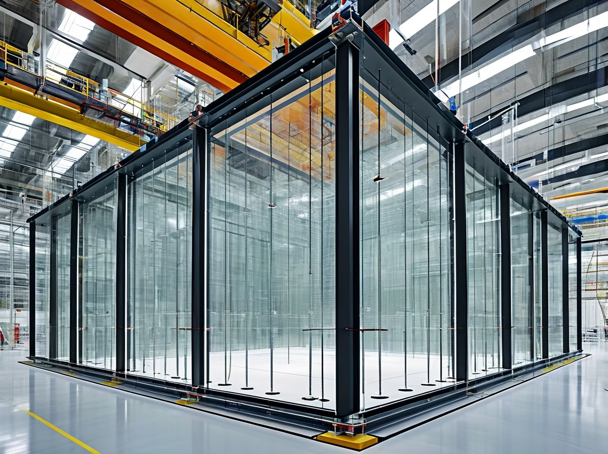
- Full-scale mock-up testing — a representative bay (or bays), typically at least two storeys high and two bays wide, built by the actual installing contractor using production components and tested in an accredited laboratory. This is the default for bespoke or unitised systems, tall towers, complex geometry, mixed cladding interfaces, and anything in a cyclonic or hurricane region. It catches tolerances, sequence problems, interface leakage between the curtain wall and adjoining elements, and drainage failures that component testing cannot.
- Wind tunnel studies — a boundary-layer wind tunnel on a scale model of the building and its surroundings. These derive site-specific external pressure coefficients rather than relying on code-generated coefficients. They are justified for buildings with unusual massing, slender proportions, adjacent taller buildings, or where code coefficients are conservative to the point of over-designing the system. The outputs feed directly into the structural design pressures used for the full-scale test.
Accredited Laboratories and What Accreditation Means
A test report is only as credible as the laboratory that produced it. Third-party accreditation means an independent body has audited the laboratory’s quality system, equipment calibration, traceability of instrumentation and competence for the specific test methods listed on its scope. Relevant bodies include IAS and A2LA (United States), UKAS (United Kingdom), CNAS (China), NATA (Australia) and the national members of the ILAC mutual recognition arrangement.
Always check the test methods on the laboratory’s accredited scope. A laboratory accredited for air permeability is not automatically accredited for dynamic water testing or structural performance. A report from a manufacturer’s internal test rig, even if technically competent, is not third-party verification.
Factory Production Control and Manufacturer Documentation
A specification should require the manufacturer’s factory production control documentation as a routine deliverable, not on request:
- Mill certificates for aluminium ingot and extrusion, identifying the heat number, alloy (typically 6060, 6063 or 6061 for curtain wall extrusions) and temper (T4, T5, T6).
- Mechanical property test results — tensile strength, yield strength and elongation — against the relevant standard such as EN 755 for extruded profiles.
- Coating documentation — powder or anodised coating thickness measured to the relevant standard, adhesion test results (cross-hatch or impact per EN ISO 2409 / ASTM D3359), and colour and gloss consistency.
- Accelerated weathering and corrosion results — salt spray to ASTM B117 / EN ISO 9227 and, for marine environments, cyclic corrosion results per EN 12280.
- Traceability linking finished profiles and finished assemblies back to the raw material heats.
Site Verification on the Installed Facade
Laboratory performance does not guarantee site performance. A practical verification regime ought to include:
- On-site water test on an installed section of facade, using a spray rack or calibrated nozzle assembly (AAMA 501.2, or a project-specified method) to confirm that gaskets, sealant and interfaces perform as tested. This is typically done on one or more representative bays and repeated where remedial work has occurred.
- Anchor pull tests on a sample of installed anchors and brackets to confirm the embedment, substrate condition and fixing capacity assumed in the structural calculations.
- Visual and QA inspection — systematic checks of gasket continuity, sealant depth and adhesion, transom and mullion alignment, weep and baffle placement, and pressure plate engagement, documented against the approved shop drawings.
The Documentation Package to Require Before Releasing the Package
Before a facade package is released for fabrication and installation, a specifier should require:
- Full-scale and/or component test reports from an accredited third-party laboratory, stating the methods used and the applied pressures.
- Structural calculations for mullions, transoms, anchors and brackets, with the design wind pressures, deflection limits and load combinations clearly stated.
- The supplier’s QA plan, factory production control procedures and inspection and test plan for the project.
- Coating and material certificates, including durability class and warranty coverage.
- Warranty terms with defined exclusions, particularly around water penetration, coating performance and adhesion.
- Confirmation of fire performance where relevant — for example EN 13501 classification of the assembly, and CE or UKCA marking where the product falls under the Construction Products Regulation.
Compliance Is Not the Same as Performance
Passing a wind resistance test demonstrates that a specific specimen met a specific performance specification. It does not, by itself, deliver code compliance. Fire classification and reaction-to-fire performance, structural design codes, and product marking regimes such as CE marking under the CPR or UKCA marking in Great Britain are separate requirements with their own evidence. A wind test report is one input to the compliance file, not a substitute for it. Specifiers should confirm that the product’s Declaration of Performance and applicable classification documents are in place alongside the performance test data.
Getting an Accurate Wind Load Design and Quote from Your Supplier
What to Send Your Supplier Before Anyone Can Verify the Design
A curtain wall panel is not a catalogue item. Its thickness, stiffener depth, bracket size and anchor count all follow from the wind pressure acting on it, and that pressure is a property of your project — not of the product. Until the manufacturer has the wind load case, any structural statement it makes is an assumption. Send the following in one package, ideally before requesting pricing.
- Project location and country — city and site, plus the country whose code governs. Coastal, urban, valley and open-country sites at the same nominal wind speed behave differently.
- Governing code and national annex — for example EN 1991-1-4 with a named national annex, ASCE 7 with the edition year, AS/NZS 1170.2, or a local authority code. The annex changes the national wind map, terrain categories and season factors, so “Eurocode” alone is not enough.
- Building height and geometry — overall height above ground, plan dimensions, parapets, canopies, returns, corner conditions and any unusual massing that alters local pressures.
- Terrain or exposure category — roughness class, exposure category, or a description of surroundings (open sea, suburban, dense city centre). This drives the exposure coefficient.
- Wind study status — does a wind tunnel report exist, or the structural engineer’s own calculation? If yes, send it. If no, state that the supplier must derive pressures from the code, and confirm who signs off.
- Net design pressures by zone, in kPa — the critical part. Ideally supplied separately for panel, mullion, transom, bracket and anchor, and split into positive and negative (suction) values. Suction at corners and edges is almost always the governing case; a single average figure hides it.
- Deflection limit — the acceptance criterion for mullions and panels, commonly expressed as a fraction of span or in mm, and whether it is a serviceability or airtightness-driven limit.
- Panel module sizes and clear spans — the actual grid, plus the clear span between supports. A nominal module size is not the same as the structural span if there are intermediate supports.
- Support condition — simply supported, continuous, double-span, or a fixed detail; and whether dead load is carried by brackets, mullions or a separate system.
- Alloy and temper preference — if the specification names one, say so; if not, ask the supplier to propose and justify it.
- Finish system — anodised, powder coated or PVDF, with thickness class. Coating and pretreatment affect edge detailing and handling rather than strength, but they change the drawing package.
- Live load and inter-storey drift — required maintenance or access loading, and the design drift ratio the frame must accommodate without distress or loss of weather seal.
- Seismic category, if applicable — the category or design acceleration, which governs connection ductility and movement joints rather than panel strength.
- Target test evidence — which tests and which standard you expect: air permeability, watertightness, wind resistance (structural and safety), inter-storey drift, and seismic. State whether it is a project mock-up or a system test report.
Why “Give Me a Price Per m²” Cannot Be Answered Accurately
A price per square metre is a price for a design, and the wind load case is that design. Change the pressure zone from a low-rise inland site to a tall coastal building and the aluminium profile depth, the bracket gauge, the anchor diameter and the anchor count can all change — sometimes the whole framing family changes. A supplier who quotes from a square-metre rate with no load data has done one of two things, and neither is good for you.
Either the quote carries an unpriced risk: the supplier builds in a worst-case allowance your project never needed, and you pay for structure you do not require. Or the quantity is priced on a light assumption and the real design emerges during drawing approval, at which point the honest supplier asks for a variation and the dishonest one reduces a bracket to hold the number. The second outcome is the dangerous one, because it does not surface as a cost — it surfaces as a deflecting mullion, a leaking corner or a failed mock-up.
Either way, the comparison you thought you were making between three suppliers was never a like-for-like comparison. The correct move is to issue the load case first, then ask each supplier to price the same design basis and state the assumptions it used.
What a Competent Manufacturer Does With the Load Case
Given the package above, the engineering response should be traceable:
- Internal structural check to EN 1999-1-1 or the governing code for the project, calculating panel bending and deflection, mullion and transom stress and deflection, and bracket reactions.
- Alloy and temper selection — typically a 6xxx-series extrusion in a temper suited to the required strength and the bending method, with the choice justified against the calculated demand rather than habit.
- Bracket capacity verification against the anchor schedule, including edge distance, substrate type (concrete, steel, or a specific embedment) and the interaction between wind suction, dead load and any eccentricity.
- A written submission drawing showing the elevation with the pressure zone diagram overlaid, member sizes, bracket details and anchor positions, so the design intent can be checked against the engineer’s numbers.
- A pre-production or mock-up sample, built to the approved drawing and tested where the specification requires it, before full production is released.
Regional Sourcing Nuances
Buyers comparing suppliers across regions should expect different documentation expectations, even for the same technical performance.
| Buyer region | Typical expectation |
|---|---|
| Europe | EN-standard test evidence and CE marking under the relevant harmonised standard, or UKCA for the UK market; full EN 1991-1-4 / EN 1999-1-1 design documentation |
| North America | AAMA-based test evidence and ASCE 7 load derivation, with imperial module conventions and adoption of the local building code in the relevant state or province |
| Middle East and Southeast Asia | Often a hybrid: BS or EN design standards applied alongside local authority requirements, with test evidence accepted from recognised third-party laboratories |
Two practical frictions recur. Metric and imperial module conventions do not translate cleanly — a nominal 1,500 mm module is not a 5 ft module, and glass and frame sizes have to be re-based rather than converted. And the recognisable test evidence differs: a report that satisfies a European reviewer may not be the report a North American reviewer expects, even when both demonstrate the same structural capability. Ask early which evidence will be accepted, so the testing is scoped once.
The Sequence, So You Can Programme It
Ordering a bespoke curtain wall follows roughly this chain: engineering review and design confirmation, prototype or pre-production sample, a test slot at a third-party laboratory where testing is specified, then release to production. Each step depends on the previous one and each requires your approval before it can close — drawing approval in particular is a common cause of slippage, because the supplier cannot cut metal until the drawing is returned.
Build the programme around the sequence rather than around a single total figure. Establish who approves the submission drawing and how quickly, book the laboratory slot as soon as the prototype is confirmed, and remember that a change to the wind load case or zone pressures after prototype release resets the design work. The earlier the load case is fixed, the less of this chain has to be repeated.
Questions to Ask Any Cladding Supplier About Wind Load
- Which code and national annex will you design to, and which edition?
- How did you derive the zone pressures, and will I receive a pressure zone diagram with the submission drawing?
- What deflection limit did you apply to the mullions and panels, and who set it?
- How is the bracket capacity verified against my anchor schedule and substrate?
- Which tests will you run, at which laboratory, and to which standard — and does that evidence meet my authority’s requirements?
- What changes in your design between the pressure at the mid-zone and the pressure at a corner?

 English
  Français
  Bahasa Indonesia
  Deutsch
  Italiano
  Español
  العربية
  Español de México
  Nederlands
  香港中文
香港中文