
Expansion joints are the part of an aluminium curtain wall that most specifications under-describe and most site defects trace back to. A facade bay moves several millimetres across a normal day; over a 30 m run that movement can exceed 40 mm. This guide covers why aluminium curtain walls need expansion joints, the different joint families and where they belong, how far apart joints should be spaced, the sealing details that actually keep water out, site tolerance control, and the specification and maintenance questions worth asking before a facade package is awarded.

Why Aluminum Curtain Walls Need Expansion Joints
Aluminium has a linear coefficient of thermal expansion of approximately 23.1 × 10⁻⁶ per °C — roughly twice that of steel and about three times that of concrete. In a curtain wall that coefficient applies to every member in the system: mullions, transoms, pressure plates, cover caps, and the panels they capture. A facade does not need to be unusually tall for the resulting movement to become a governing design condition.

The basic calculation is ΔL = α × L × ΔT. For a continuous aluminium run 30 m long subjected to a 60 °C temperature differential — realistic for a dark-anodised or dark-coated facade in southern or central Europe, where surface temperatures can pass 70 °C in summer sun and fall below −10 °C in winter — the free movement is:
ΔL = 23.1 × 10⁻⁶ × 30,000 mm × 60 °C ≈ 41.6 mm
That is over 41 mm of movement, split approximately evenly about the system’s fixed point: around 20.8 mm of expansion and 20.8 mm of contraction. If that movement is prevented, the restraint force is not small. For a typical mullion section of 800 mm² with E = 70,000 N/mm², a fully restrained 60 °C thermal strain implies a notional stress near 97 N/mm² — roughly 78 kN per mullion, far beyond what brackets, anchor bolts or slab-edge fixings can take. In practice the system will not develop that force; it will buckle, twist, open at joints, tear sealant or fatigue fixings instead.
Restraint and movement in the structural frame
The structural frame moves too, but on a different profile. A 30 m concrete frame experiences roughly 9–11 mm over the same 60 °C, and a steel frame around 21 mm. More importantly, frames also move with creep, shrinkage and long-term settlement that aluminium does not share, and slab edges deflect under live load. A curtain wall anchored to that frame therefore receives three separate inputs: its own thermal movement, the frame’s movement, and inter-storey drift. EN 13830 requires these to be addressed in the system design rather than absorbed by the cladding.
Why the wall must move independently
The clean engineering answer is to fix the curtain wall at a single point — usually one anchor per mullion at a defined slab, or a dedicated fixed point per movement zone — and let every other connection slide or rotate. Brackets are detailed with slotted holes, PTFE or nylon sliding pads and clearance to the bolt shank, sized from the calculated movement plus erection tolerance. Vertical movement is taken up in the panel joints or in a dedicated movement joint; horizontal movement is taken in the vertical joints between mullions. A curtain wall rigidly tied at every floor becomes a shear diaphragm against the frame, which is neither its structural role nor a condition any glass or gasket system is tested for under ASTM E330 or AAMA 501.
Joint Types: Vertical, Horizontal, Corner and Seismic Movement Joints
Specifications often blur four distinct joint families that behave differently and sit in different parts of the facade. Getting the terminology right matters, because the wrong joint in the wrong place either leaks or locks up.
Inter-panel expansion joints
These are the joints within the panel field: vertical joints between adjacent mullions and horizontal joints at transoms. They absorb the movement of individual panels and frame members and are typically 12–20 mm wide, sealed with a backer rod and a low-modulus silicone. In stick systems they also absorb erection tolerance. They are not designed to take the movement of a whole 30 m facade run — that would need an impractical joint width.
Movement joints at floor slab lines
Where a curtain wall spans multiple storeys, horizontal movement at each slab line is normally handled by the stack joint: the transom at the slab edge is detailed so the mullion above can slide vertically within a gasketed receiver, or the transom is split into two interlocking profiles with a gap. This is the standard location for vertical facade movement in unitised systems. Where the frame itself has a structural movement joint, the curtain wall needs a matching vertical movement joint on the same line, typically 40–100 mm wide, with a cover cap or bellows detail and a continuous internal baffle.
Corner and seismic joints
At building corners and returns, two facade planes meet and each moves in its own direction. Corner joints need a sliding or articulated detail rather than a simple sealant bead, and often a proprietary corner mullion with an internal movement allowance. Seismic movement joints are separate again: AAMA 501.4 and 501.6 address inter-storey drift and racking, and the joint detail at a seismic separation must accommodate both drift and the seismic gap of the structure — typically 50–150 mm — without the glass edge coming into contact with the frame.
Perimeter and fire-stop joints
At the head, sill and jambs the curtain wall meets structure that moves differently. These perimeter joints are usually 15–25 mm and are filled with mineral wool and a fire-rated sealant where a compartment line is crossed. They are movement joints as well as fire-stop joints, so the sealant must be selected for the movement class, not only for the fire rating.
Expansion Joint Spacing: How Far Apart Should They Be?
No code mandates a single spacing for expansion joints in aluminium curtain walls. EN 13830 sets performance requirements but leaves joint spacing to the system design, and the practical rule is driven by three constraints: the movement the joint can absorb, the length of aluminium that can be manufactured and handled, and the module logic of the facade.
Rules of thumb
- Panel field joints every 3–6 m, aligned with the structural grid and the module width.
- A dedicated horizontal movement joint at every slab line in multi-storey facades — the default, not the exception.
- A dedicated vertical movement joint wherever a continuous facade run exceeds roughly 12–15 m without an interrupting corner, return or structural joint.
- Always at building structural movement joints, and at transitions between structurally independent building elements.
The 3–6 m logic is not arbitrary. Standard aluminium extrusion stock lengths are 6.0 m (sometimes 6.5 m), and mill-finish or anodised profiles are shipped and handled at that length. A 6 m module keeps one mullion per stock length with minimal offcut, and matches typical structural bay spacing of 6 m or 7.5 m. The joint width then follows from the movement calculation: a joint absorbing the movement of a 6 m panel over 60 °C needs 23.1 × 10⁻⁶ × 6,000 × 60 ≈ 8.3 mm of free movement, plus sealant strain capacity and tolerance. A 12–15 mm joint at 6 m spacing is therefore conservative and standard.
The important distinction is between a joint that merely separates panels and a joint designed to take accumulated movement. Where a long run of panels is continuous — a 30 m facade with no corner — the joints between panels must cumulatively absorb the run’s movement, or a dedicated movement joint has to be introduced. The table below gives indicative joint widths for sealant joints at a fixed point, assuming a low-modulus silicone at 25% movement capability and a 60 °C differential.
| Facade run (fixed point to joint) | Movement at 60 °C ΔT | Indicative joint width | Typical detail |
|---|---|---|---|
| 3 m | 4.2 mm | 10 mm | Standard field joint |
| 6 m | 8.3 mm | 12–15 mm | Field joint at module line |
| 12 m | 16.6 mm | 20 mm | Field joint or sliding mullion |
| 18 m | 24.9 mm | 25–30 mm | Dedicated movement joint |
| 24 m | 33.3 mm | Cover cap / bellows | Dedicated movement joint |
| 30 m | 41.6 mm | Cover cap / bellows | Dedicated movement joint, fixed point at mid-length |
Beyond roughly 20 mm of required movement a sealed butt joint becomes impractical: the depth-to-width ratio is hard to hold, the joint looks heavy, and the risk of adhesive failure rises. At that point the detail should move to a mechanical movement joint with a cover cap, articulated gasket or bellows, sized for the full calculated movement plus erection tolerance and seismic allowance. Joint widths should always be confirmed by calculation for the project’s actual temperature range, panel colour and orientation, and checked against the sealant manufacturer’s declared movement class.
Sealing Details That Actually Work
A movement joint in a curtain wall is first a weather seal and only second a movement device. Joints that leak rarely fail because the sealant was the wrong brand; they fail because the sealing principle was wrong. The most reliable approach in European facade practice is two-stage sealing derived from the rainscreen principle: an outer rain screen that sheds the bulk of the water and an inner air seal that closes the pressure boundary. The two stages are separated by a drained and ventilated cavity. Water that passes the rain screen — through capillary action, wind-driven rain or a failed gasket splice — is intercepted in the cavity and drained back out rather than reaching the air seal under pressure.
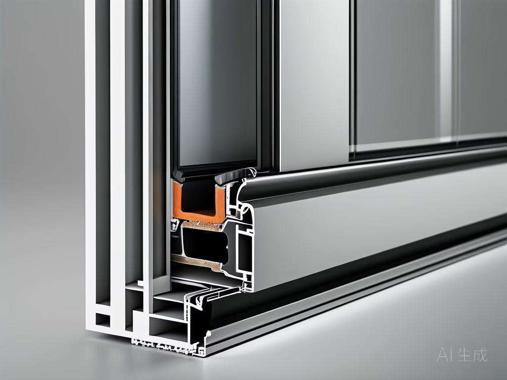
Stage one is normally a gasket or a wet-sealed cover cap at the outer face. Stage two is the continuous air seal at the back of the joint, which must be continuous around corners, at sill and head conditions, and where the joint meets the slab edge. In EN 13830 terms the air seal is part of the air permeability performance of the facade, and it should be continuous with the air barrier of the adjacent wall assemblies. A common specification error is to treat the visible sealant bead as both stages; when that single bead cracks there is no second line of defence.
Gaskets versus wet seals
Both approaches have a place, and the choice should follow the movement and access regime of the joint rather than installer preference.
- EPDM gaskets — the default for unitised systems and joints with predictable, repeated movement. Standard compounds are specified to ISO 3302-1 class E tolerances, with hardness around 60–70 Shore A and compression set below 25% after 22 h at 70 °C. They handle UV, ozone and the European temperature range well but are not resistant to sustained contact with oils and solvents.
- Silicone gaskets — specified where high UV exposure, high service temperature or aggressive cleaning regimes are expected. They cost more and have lower tear strength, so they need generous bulb geometry and careful site handling.
- Wet seals — one- or two-component silicone sealants, used at site-applied joints, at interfaces to other trades and where a gasket cannot fit the geometry. Wet seals demand correct substrate preparation, primer where specified and a properly dimensioned joint. They tolerate irregular joint width better than gaskets, but only within their movement class.
Splices in gaskets are the single most common weak point in stage one. A mitred or butt splice should be a vulcanised or mechanically locked splice, not simply pushed together. Corners should be factory-moulded where possible. Where site splices are unavoidable, specify an adhesive and splice geometry approved by the gasket manufacturer, and require a water test of the spliced assembly before sign-off.
Backer rod and joint geometry
A wet seal only performs if the joint has the correct width-to-depth relationship. The backer rod sets the sealant depth and provides the bond-breaker that prevents three-sided adhesion. The practical rules are well established:
- Backer rod diameter at least 25% larger than the joint width, so it compresses and grips the joint faces without falling into the gap.
- Sealant depth approximately half the joint width, minimum 6 mm and normally capped at 12–15 mm for facade joints. Deeper sections do not improve performance and can fail by cohesive tearing.
- Width-to-depth ratio generally between 1:1 and 2:1, targeting about 2:1 where significant movement is expected.
- Sealant tooled to a concave profile, which reduces stress at the bond line and sheds water.
The sealant must be selected for the movement it will actually see. ISO 11600 classifies sealants by movement capability — for example class 25 LM or class 50 LM for low-modulus silicone — and ASTM C920 uses movement classes such as ±25% and ±50%. The percentage refers to total movement relative to the installed width, usually quoted as ±, so a ±25% sealant accommodates total movement of 25% of the joint width, taken as ±12.5% about the installed dimension.
This is where specification errors show up on site. Take a 20 mm joint experiencing 6 mm total movement between thermal and structural extremes. Six millimetres is 30% of 20 mm, while a ±25% class sealant is rated for 25% of the joint width — 5 mm on a 20 mm joint. The 6 mm movement is outside its capacity. It will not necessarily fail on the first cycle, but the sealant runs past its fatigue limit and adhesion or cohesion failure follows within a few seasons. The answer is either to widen the joint so the movement falls inside the class, or to step up to a ±50% class sealant — and even then the installation depth, primer and bond-breaker still have to be right.
| Parameter | Typical requirement | Standard or basis |
|---|---|---|
| Joint width, facade movement joint | 20 mm nominal, 10 mm minimum | Project-specific; EN 13830 performance context |
| Sealant depth | 0.5 × width, min. 6 mm, max. 12–15 mm | Manufacturer installation guidance |
| Width-to-depth ratio | 1:1 to 2:1, target 2:1 | Industry practice |
| Backer rod diameter | ≥ 1.25 × joint width | Manufacturer guidance |
| Low movement class | ±25% (ISO 11600 class 25; ASTM C920 ±25) | ISO 11600; ASTM C920 |
| High movement class | ±50% (ISO 11600 class 50; ASTM C920 ±50) | ISO 11600; ASTM C920 |
| EPDM gasket hardness | 60–70 Shore A | Manufacturer data; ISO 3302-1 tolerances |
| EPDM compression set | ≤ 25% after 22 h at 70 °C | Manufacturer test data |
Finally, specify the sealant by class and by tested compatibility with the actual substrates — anodised aluminium, powder-coated aluminium, glass, and any membrane or flashing it touches. AAMA 800 provides a useful framework for evaluating sealant performance and compatibility on facades and should be referenced alongside the ISO and ASTM classifications.
Common Failure Modes and How to Prevent Them
Movement joint failures are repetitive. Eight or so mechanisms account for most defects seen in service, and each has a known preventive measure that can be written into the specification or the inspection regime.
Adhesion loss and three-sided adhesion
Adhesion loss usually starts at the bond line and is often mistaken for a sealant problem when it is a preparation problem. Dust, release agents, protective film residue, moisture and low surface energy are the usual culprits. Three-sided adhesion — where the sealant bonds to both joint faces and also to the backer rod or joint base — is the classic geometric error. It removes the free surface the sealant needs in order to stretch and converts movement directly into tensile stress at the bond line. The remedy is a bond-breaker: a polyethylene backer rod, bond-breaker tape, or a joint detail with a free back face. Specify the bond-breaker explicitly and inspect for it before sealant is applied.
Sealant tearing at corners
Corners concentrate movement and are usually where a joint first opens. A sealant tooled into a sharp internal corner has a stress raiser exactly where the stress is highest. The fix is a radiused or chamfered corner detail, a movement joint that continues around the corner rather than terminating into it, and — in high-movement locations — a pre-formed corner piece or gasket corner moulding instead of a site-applied bead.
Gasket compression set and water pooling
Gaskets that are over-compressed during installation, or compressed against a rough or contaminated surface, take a permanent set and lose contact. The result is a joint that looks closed but is not sealing. The remedy is correct groove geometry, compression controlled within the manufacturer’s stated range — commonly 20–35% of the gasket section — and clean mating surfaces. Water pooling in open joints is a drainage problem, not a sealing problem: joints open to the weather must be detailed so water can escape, with positive fall and a weep path, never a flat or back-sloping pocket.
Oil bleeding and plasticizer migration
Oil bleeding appears as an oily film or dark stain on aluminium and adjacent surfaces, often spreading from a gasket or sealant. It is caused by incompatible materials — typically a plasticised compound in contact with a material that absorbs or reacts with the plasticiser — and it can attack powder coatings and anodised finishes. The prevention is a written compatibility statement from the gasket and sealant manufacturers covering contact with the specific aluminium finish, plus avoidance of plasticised materials wherever they touch the facade. Where migration has already occurred, the affected components usually need replacement rather than cleaning, because the source keeps migrating.
Contamination from protective film
Protective film left on aluminium panels or extrusions is a frequent and entirely avoidable cause of adhesion failure. Film residue, adhesive and trapped moisture prevent the sealant or gasket from bonding, and the film itself can hold water against the joint. Specify a film-removal and surface-preparation procedure before sealant application, with a defined removal window and a solvent wipe where the manufacturer requires it, and make it a hold point in the inspection plan.
Tolerance stack-up and uneven joint widths
Installation tolerance stack-up is the least visible failure mode but one of the most consequential. If the frame, slab edge, brackets and panels all sit at opposite ends of their permitted tolerances, joint width at one end of a run can be well outside the design assumption. A joint designed at 20 mm may arrive at 14 mm or 26 mm. The sealant class is then no longer adequate and the backer rod may not fit properly. Prevent it by stating joint width tolerances explicitly, requiring an as-built joint width survey before sealant is ordered, and designing for the worst-case stack-up rather than the nominal.
| Failure mode | Root cause | Corrective action |
|---|---|---|
| Adhesion loss | Contaminated or damp substrate; missing primer; incompatible surface | Clean and dry substrate; apply specified primer; verify compatibility; site adhesion test |
| Three-sided adhesion | Sealant bonded to backer rod or joint base | Install bond-breaker or polyethylene backer rod; inspect before sealing |
| Sealant tearing at corners | Sharp internal corner; movement concentrated at a stress raiser | Radius corner detail; continue movement joint around corner; pre-formed corner piece |
| Gasket compression set | Over-compression; rough or contaminated mating surface | Correct groove geometry; control compression; clean surfaces |
| Water pooling in open joints | Flat or back-sloping joint; blocked or missing weep path | Detail positive fall; weeps at low points; verify drainage at mock-up |
| Oil bleeding / plasticizer migration | Incompatible plasticised component against the finish | Require compatibility statement; substitute non-migrating components; replace affected parts |
| Protective film contamination | Film or adhesive residue left on panels before sealing | Define film removal and surface prep procedure; make it an inspection hold point |
| Uneven joint widths | Frame, slab, bracket and panel tolerances accumulating | State joint width tolerances; survey as-built widths; design for worst case |
Waterproofing and Drainage at Movement Joints
A movement joint is also a drainage feature, and it should be detailed as part of the facade’s pressure-equalised system rather than as an isolated gap. The objective is to keep the air seal dry and unpressurised and to give any water that enters the joint a defined route back outside.
Pressure-equalised cavity at the joint
The cavity behind the rain screen at a movement joint should be connected to the exterior through openings that allow pressure equalisation while limiting water entry. Baffles at the rain-screen line break up wind-driven water and reduce the momentum of droplets entering the cavity. The air seal, set back from the rain screen, closes the pressure boundary — so it is not exposed to full wind pressure and is not asked to resist water under pressure, only the small differential across the cavity. In EN 13830 testing terms this is what allows the assembly to meet watertightness requirements even though the outer joint is open to the weather.
Drainage path and weep positions
Drainage must be continuous and must terminate at a weeper that is visible and maintainable. Specify:
- Positive fall, typically 1:20 or steeper, along horizontal joint runs and in sill sections.
- Weep holes or slots at the low points of every drained compartment, typically spaced 400–600 mm along sills and provided at every compartment boundary.
- Baffles or upstands inside the cavity so water cannot travel laterally past a weeper without draining.
- Weepers positioned so they are not blocked by gaskets, sealant or adjacent construction, and stay accessible for inspection.
Air seals at the rain-screen line
Air seals must be continuous around the joint, at head and sill, and at the interface with the slab edge. Any break in the air seal turns the cavity into a pressurised leak path. Specify a continuous air seal — membrane, sealant or gasket — compatible with the adjacent air barrier, and require a continuity inspection at every corner and penetration. In unitised systems the air seal at the interlock is often a gasket that engages as units are brought together; in stick systems it is typically a wet seal or membrane. Either way, continuity matters more than the material.
Fire-stop integration at slab edges
Movement joints at slab edges must accommodate both the facade movement and the fire-stop, which is itself a movement joint inside the cavity. The fire-stop — typically mineral wool with an intumescent or sealant facing — must be installed without restricting the designed movement, and the perimeter barrier must remain continuous with the slab and the facade. Specify the fire-stop as a tested system for the actual slab-edge condition and coordinate its installation with the facade brackets so that neither is compromised. The air seal and the fire-stop are separate functions and should not be merged into one component unless the tested system explicitly permits it.
Typical detail stack-up, outside to inside
A workable detail at a vertical movement joint in a unitised facade usually reads from the exterior inward as follows:
- Outer rain screen: cover cap or gasket, with a controlled gap that admits water but breaks wind pressure.
- Pressure-equalised cavity: drained and ventilated, with baffles at the rain-screen line.
- Second rain screen or deflector: a membrane or flashing intercepting water that reaches the inner zone.
- Air seal: continuous, at the inner face of the joint, bonded to the air barrier on both sides.
- Fire-stop at slab edges: mineral wool and facing, tested for the condition, coordinated with brackets.
- Inner finish and substrate: continuous with the wall air barrier, with the movement joint carried through the lining where required.
Each layer has a single job, and the specification should name the material, the standard it is tested to and the inspection hold point for each. A joint detailed this way will tolerate the movement, shed the water and remain serviceable even when one layer is damaged — which is the practical definition of a sealing detail that works.
Installation and Tolerance Control on Site
Expansion joints only perform as designed if the installed gap matches the assumed gap. A joint detailed at 20 mm but built at 8 mm has lost more than half its movement capacity before the building is occupied. Site control therefore has to be a designed activity with measured hold points, not something the installer resolves by eye.
Allowable tolerances on joint width
The default acceptance band for expansion joint width is ±5 mm on the specified nominal dimension, measured perpendicular to the joint faces. On joints narrower than 15 mm, ±3 mm is more realistic; on joints wider than 40 mm, ±5 mm still applies because the constraint is usually setting-out rather than fabrication. Two further conditions belong in the specification:
- Deviation from nominal must not consume the design movement reserve. If the sealant is rated ±50% and the joint is 20 mm, the practical build range is roughly 14–26 mm; the ±5 mm tolerance has to sit inside that window, not add to it.
- Uniformity matters as much as absolute width. Adjacent joints should not differ by more than 3 mm, because visual irregularity reads as poor workmanship long before it becomes a watertightness problem.
Setting out and sequence
Establish primary control with a laser level or total station on the structural grid, then transfer to bracket lines and joint centrelines using piano wire or a taut setting-out line at each floor. Do not set out from the previous panel — errors accumulate. Mark joint centrelines on the slab edge or a continuous reference line and check them against the structural survey before the first unit is hung.
Install in a consistent sequence, typically bottom-up per elevation and in a single direction per floor, so accumulated stack tolerance is pushed into a designated adjustment zone rather than distributed at random. Where the design provides a movement or adjustment panel, hold it until the floor is complete, then close the joint to nominal.
Temperature at time of installation
Aluminium moves about 23 × 10⁻⁶ per °C; a 6 m mullion changes length by roughly 1.4 mm for every 10 °C. A gap measured at 08:00 on a cold frame will close measurably by mid-afternoon once solar gain reaches the facade. Record substrate and ambient temperature when setting out and again when sealing, and specify that joint widths for sealing are checked within a defined temperature window or corrected to the reference temperature used in the design, commonly 20 °C. On dark-anodised or dark-coated profiles in direct sun, surface temperature can exceed ambient by 20 °C or more, which is enough to distort a closure measurement.
Acceptance checklist
Check each joint at four positions — top, bottom, left and right of the panel perimeter — with a calibrated taper gauge or digital calliper, not a folding rule. Record values against grid reference rather than as a pass/fail tick.
| Check item | Method | Acceptance criterion |
|---|---|---|
| Joint width, nominal | Taper gauge or calliper at top, bottom, left, right of each panel | Nominal ±5 mm |
| Joint width uniformity | Compare adjacent joints on the same elevation | Difference ≤ 3 mm |
| Alignment / straightness | Setting-out wire or laser over full storey height | Deviation ≤ 2 mm over 3 m |
| Residual movement reserve | Compare measured width against sealant movement class | Within declared range at both design extremes |
| Backer rod depth and position | Visual and depth probe before sealing | Correct depth; bond-breaker intact; no punctures |
| Substrate before sealing | Wipe test; moisture and temperature reading | Clean, dry, within sealant application limits |
| Sealant profile | Visual and tooling check | Concave profile, no voids, correct width-to-depth ratio |
| Fire-stop continuity | Visual at each floor slab junction | Unbroken, correct product, correctly compressed |
| Installation temperature record | Ambient and substrate thermometer logged | Within specified range; recorded per elevation and date |
Sealing should not begin until the joint width survey has been signed off. Sealing over an out-of-tolerance gap locks the defect in and usually transfers the cost of remediation from the installer to the sealant warranty.
Specification Checklist and Questions to Ask Your Supplier
Most expansion joint failures on curtain walls trace back to a specification that named a product but not a performance, or to documentation that was never requested at tender stage. The specification should define measurable requirements, and every requirement should have a named document that proves it.
What the facade specification must state
- Joint widths — nominal, minimum and maximum at each location, with the design temperature range and the movement calculation that produced them.
- Movement capability — expressed as ±% of joint width at the stated service temperature range, not as a single figure.
- Gasket material — EPDM, silicone or TPE, with hardness, compression set and colour stability requirements; state whether gaskets are structural or weatherseal only.
- Sealant class — ISO 11600 classification (for example F 25 LM for a low-modulus facade sealant with ±25% movement), plus substrate-specific adhesion requirements.
- Fire-stop type — tested system, fire rating and movement capability of the fire-stop itself, since a rigid fire barrier at a movement joint is a common and serious conflict.
- Maintenance interval — the interval assumed in the durability statement and the inspection regime the warranty depends on.
Requirement and documentation matrix
| Requirement | What to ask for |
|---|---|
| Sealant performance | Current datasheet with movement class, modulus, Shore A hardness, skin formation time and service temperature range |
| Adhesion to actual substrates | Adhesion and peel test reports on the specific anodised, powder-coated or PVDF finish used, not a generic aluminium substrate |
| Movement capability | Third-party certificate to ISO 11600 or equivalent, including test temperature and cycling regime |
| Weathertightness of the joint detail | Mock-up test results for air permeability, watertightness and structural performance to EN 12154, EN 12155 and EN 12179 on a representative assembly |
| Fire-stop system | Test report to EN 1366-4 with the movement capability of the tested system, plus exact components and installation instructions |
| Gasket durability | Ageing and compression-set data; evidence of colour stability under UV exposure |
| Compatibility | Written confirmation of compatibility between sealant, gasket, backer rod and adjacent finishes |
| Warranty and service life | Declared service life, warranty terms and the maintenance conditions the warranty depends on |
Ask for the mock-up to include at least one movement joint at full height, tested at both the minimum and maximum design width. A joint that passes at nominal width and fails at the extreme has not really been tested. Where a supplier cannot produce substrate-specific adhesion data, request a site adhesion test on the first completed elevation and make the result a formal hold point.
Maintenance and Service Life
Expansion joints are consumable components. The curtain wall frame will outlast the sealant by decades, and the maintenance plan should reflect that from day one rather than treating joint failure as a warranty event.
Inspection intervals
Carry out a full visual inspection 12 months after completion, then annually for the first five years, then every two to three years where conditions are benign. Increase to annual or six-monthly for facades exposed to heavy pollution, marine atmospheres, driving rain or large diurnal temperature swings. Inspect after any significant storm or impact event, and always before the warranty expires so latent defects are still actionable.
What deteriorates first
In practice the sequence is predictable:
- Sealant adhesion at the bond line — usually the first sign, appearing as peeling, loss of contact at the arris, or water tracking behind the bead.
- Surface crazing and chalking — cosmetic at first, then a route for water ingress and UV degradation of the bulk material.
- Gasket compression set — weatherseal gaskets lose sealing force at corners and at mullion-to-transom junctions before anywhere else.
- Backer rod displacement — rod migration creates three-sided adhesion, which converts a moving joint into a stressed bead and causes premature rupture.
- Fire-stop degradation — often invisible until demolition or a compartmentation survey, hence the need for recorded inspection points at slab edges.
Replacement cycle and cost
Plan on replacing facade sealant at 10–15 years, with the first full replacement usually closer to 12 years on exposed elevations. Replacing joints across a large facade is a significant cost: budget for access — scaffold, mast climber or rope access — as the dominant item, often 50–70% of the total, with sealant removal, substrate preparation and re-sealing making up the rest. Replacing joints in one planned campaign is considerably cheaper than repeated call-outs for isolated leaks.
Access and record keeping
Design for maintenance: provide anchor points or davit sockets for rope access, make sure joints are reachable without removing panels, and avoid details where a joint can only be serviced from inside a finished ceiling void. Record keeping should be permanent and specific — a joint register by grid reference, with sealant product, batch, installation date, installation temperature, measured widths and every subsequent inspection finding. When a joint fails in year eight, that register is the difference between a targeted repair and a survey of the entire facade.

 English
 Français
 Bahasa Indonesia
 Deutsch
 Italiano
 Español
 العربية
 Español de México
 Nederlands
 香港中文